
We deliver from stock within 2-3 days, and for custom orders within 1-2 weeks.
In urgent cases, please call us!


If we look back at the changes in fireplace trends in Hungary over the past quarter of a century, one important conclusion can certainly be drawn: user expectations and manufacturers’ offerings have evolved from an initial focus on visual appeal and atmosphere to the economical heating of an entire house. It is safe to say that fireplaces have earned a well-established place among the popular types of wood-burning heating appliances.
Unfortunately, even in professional circles it is still often claimed—particularly by supporters of tiled stoves—as an argument against fireplaces that the flue gas leaves through the chimney at an excessively high temperature, and therefore the 70-80% efficiency advertised by fireplace-insert manufacturers cannot be genuine. Opinions of this kind, in such a simplified form, may sound convincing to a layperson. As a professional argument, however, they are incorrect, even if they appear plausible at first sight.
Let us examine the full picture in more detail. The nominal output of fireplace inserts is determined by the size of the heat-emitting surface and the maximum temperature that this surface can reach. These values can be calculated and measured accurately. The same applies to efficiency, which is determined from measurements and calculations performed with completely clean heat-exchange surfaces, optimal chimney draft and dry hardwood, based on testing carried out in an accredited thermal engineering laboratory.
It is important to emphasize that these measurements are performed under laboratory conditions (dry wood, stable chimney draft, etc.). But what happens if, during everyday use, we overload the fireplace with wood—as almost everyone is inclined to do—and fail to take into account the increased suction effect (draft pressure) of the chimney as it heats up, which can become several times higher than the optimal value?
Naturally, in this situation we heat wastefully and lose energy, because the heat-emitting surface of the fireplace insert is unable to transfer the additional energy produced by the excess wood to the convection medium (air). The extra energy generated leaves through the chimney with flue gases at an obviously higher temperature. In this case, the skeptics are right: efficiency decreases and the fireplace becomes wasteful.
Although the operating instructions specify the optimal hourly amount of firewood, we cannot expect users to weigh each load on bathroom scales. The additional heat generated by burning excess wood does not warn the user about wasted energy either, because it does not necessarily affect their perceived comfort. Manufacturers have therefore experimented with various methods to eliminate these disadvantages by limiting the combustion-air supply in an attempt to minimize the generation of excess energy. This has not proved to be a successful solution, because during ignition users were forced to leave the fireplace door open by about a finger’s width. Unfortunately, this unprofessional practice has even been recommended by some manufacturers and distributors.
Combining air heating with heat storage
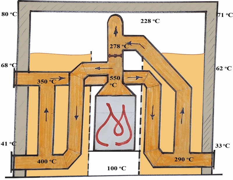
In March 2006, we tested the following then-innovative “hybrid” solution. András Költő provided the test site and measuring equipment, as well as the contractor and skilled labor, for an experiment carried out using Ben-Kel Kft.’s design, technical solutions and fireplace insert. Figure 1 shows the essential principle of the technical solution in an unfolded layout.
Figure 1
According to the original design, a 7 m long single-pass flue assembled from pipe fittings was to be fixed inside a sheet-steel tank on each side of the centrally positioned cast-iron air-heating fireplace insert, after which the tanks would be filled with quartz sand. The sand allows the entire void to be filled while also permitting the flue pipes to expand under the effect of heat. A mechanically operated diverter valve provides a direct route for the flue gases, thereby preventing possible smoke backup during ignition. Once the chimney has warmed up (10-15 minutes), turning the diverter forces the flue gases along the extended route. Cleaning openings are provided in the horizontal sections of the flue passage.
Unlike the original design, the sand tanks were ultimately built from solid brick, as was the cladding of the entire structure. The temperatures of the flue gas, convection air, sand and the outer masonry surface were measured at 34 measuring points at 30-minute intervals. Measurements were carried out separately with the tanks filled with sand and with the tanks empty. Figure 1 shows the temperature conditions at the point in the firing cycle when the flue-gas temperature at the throat of the fireplace insert had remained at approximately its average level for a relatively sustained period.
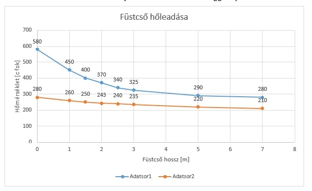
The measurements performed without sand provided a convincing answer to the question of what flue-pipe length is optimal for air-heating fireplaces. Figure 2 shows the change in flue-gas temperature as a function of flue-pipe length.
Figure 2
The lower curve shows the average change in flue-gas temperature as a function of passage length during optimal firing (3.8 kg of dry wood per hour for 12 kW output). We can see that, starting from 280°C, the heat loss of the flue gas—that is, the amount of heat transferred—remains significant up to a pipe length of approximately 2.5-3 m, but beyond this length the system becomes uneconomical. The main reason is that the temperature difference between the air heated in the convection chamber and the flue gas becomes very small. In fact, during the final stage of firing, if thermal equilibrium is reached—meaning that the convection-air temperature reaches the flue-gas temperature—the heat-exchange process stops entirely. In an unfavorable case, if the flue-gas temperature falls below that of the air surrounding the flue pipe during the final stage of firing, the direction of heat transfer is reversed. The convection chamber is then cooled as heat is transferred back into the flue gas. It should also be noted that if ventilation in the convection chamber is restricted, or if the ventilation openings are designed too small, very high temperatures develop inside the structure and thermal equilibrium between the flue gas and its surroundings is reached prematurely. In our experience, air temperatures above 300°C inside the structure are not economical, and excessive thermal loading of the fireplace insert also shortens its service life considerably.
The upper curve shows how a flue-gas temperature of 580°C at the throat changes along the flue-pipe length when excess wood is burned. All of the conclusions discussed above for optimal firing apply in this case as well. The most important lesson is that the substantial amount of heat not utilized by the fireplace insert can be recovered effectively by extending the flue pipe by 2.5-3 m. This flue-pipe length corresponds to approximately 1.5-1.8 m2 of additional heat-emitting surface, which can also be achieved in a more compact space using various design solutions.
Options for secondary heat recovery
Heat exchanger flue pipes, air heat exchangers and water heat exchangers have long been used to recover heat from flue gases.
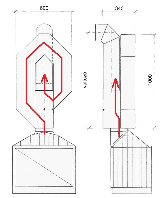
Below, we recommend several innovative products manufactured in Hungary that are also cost-effective and offer an acceptable balance of price, value and efficiency. Figure 3 shows the operating principle of the BF secondary baffle channel, which can be fitted to the flue outlet of any fireplace insert. The key advantage of this application is that it increases the heat-emitting surface within the convection chamber by 1.8 m2 without the position of the chimney connection affecting its usability. During ignition, the flue gases are allowed to leave via a direct route. After a few minutes of operation, once the chimney has warmed and the draft has increased, a diverter valve can be turned to force the flue gases along the extended route. This lengthens the flue passage and reduces the velocity of the air mass flow. The latter effect is achieved by the specially designed cross-section of the baffle channel. The passage is self-cleaning: any fly ash that forms falls back into the fireplace insert. Soot and tar deposits are effectively prevented.
Figure 3
With sufficient creativity, the additional usable energy produced can be managed in ways suited to the possibilities of the installation. For example, the heat-storage mass of the fireplace surround can be increased, convection flow can be enhanced with a thermostatically controlled fan, warm air can be routed more confidently through air ducts to other rooms in the house, and so on. A fireplace version with an integrated oven provides an increase in heat-emitting surface comparable to that of the BF baffle channel. (Figure 4)
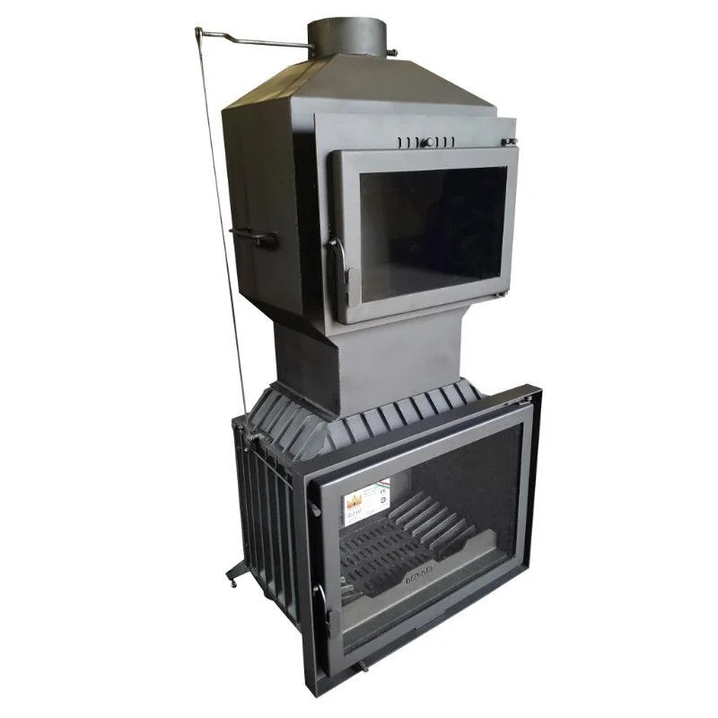
Figure 4
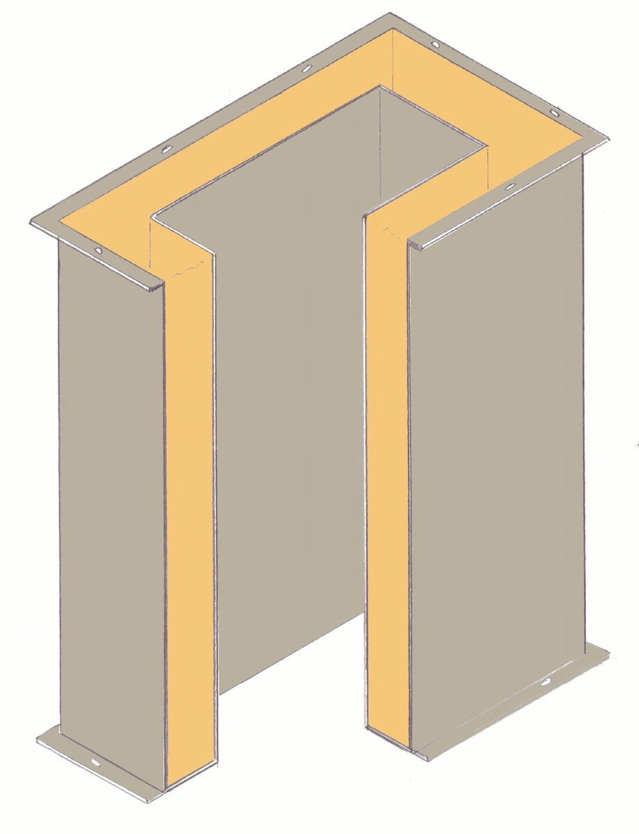
Imported secondary heat-recovery units using fireclay flue channels are not new to the industry, but their major disadvantage is their high purchase cost. Unfortunately, this significantly limits their widespread adoption. As a competitively priced Hungarian-made alternative, we recommend the fireclay-lined flue-channel heat-storage unit shown in Figure 5, with a total mass of nearly 200 kg. An important advantage is that it is assembled into its final position on site. The horizontally positioned bricks alternate the direction of the flue gases from one row to the next, slowing the flow of thermal energy and increasing the duration of heat transfer. As a result, heat release is extended over time, because the flue-channel unit above the fireplace insert begins heating the convection chamber only when the temperature of its fireclay content becomes higher than that of the surrounding air. Under favorable conditions this generally occurs after 3-4 hours of heating. The system advantageously halves the output released per unit of time while approximately doubling the duration of heat transfer.
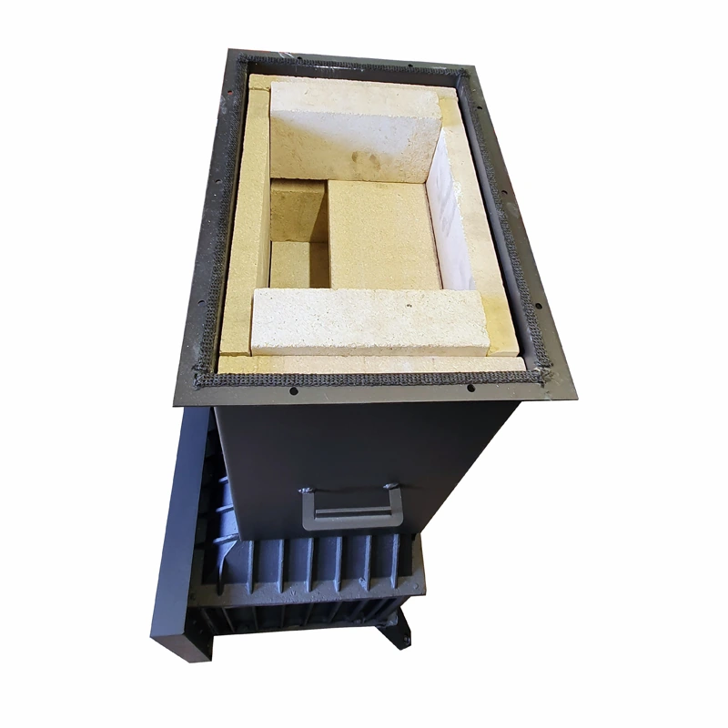
Figure 5
The Ben-Kel heat-storage unit shown in Figure 6 operates on a similar principle and can be installed on Ben-Kel fireplace inserts. In this version, the fireclay elements are replaced by quartz sand placed in a closed tank. Because sand has the same specific heat capacity as fireclay and the mass of sand used is the same, it is capable of providing the same thermal performance. Baffle elements slow the flow of the flue gases in the same way as in the fireclay version.